Are you ready to unlock the full potential of your oscilloscope? Whether you’re a beginner or just looking to sharpen your skills, knowing how to work with an oscilloscope can transform the way you analyze electronic signals.
This powerful tool lets you see what’s happening inside your circuits in real-time, helping you spot problems faster and design better projects. In this guide, you’ll discover simple, clear steps to use your oscilloscope like a pro—no confusing jargon, just easy tips that make a real difference.
Keep reading, and you’ll gain the confidence to handle your oscilloscope with ease and precision.
Credit: www.pokitinnovations.com
Oscilloscope Basics
Understanding oscilloscope basics helps you use this tool well. It shows electrical signals as waveforms. This lets you see how signals change over time. Many people use oscilloscopes in electronics, science, and engineering. Knowing the types, parts, and waveform views is important. It makes working with oscilloscopes easier and clearer.
Types Of Oscilloscopes
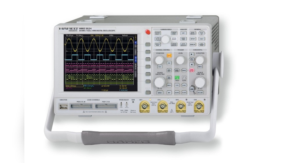
There are mainly two types of oscilloscopes. Analog oscilloscopes show signals directly on a screen. Digital oscilloscopes convert signals into numbers. Then they display the signals on a screen. Digital models offer more features and better accuracy. Portable oscilloscopes are small and easy to carry. Bench oscilloscopes sit on a desk and have larger screens. Choose the type based on your needs and tasks.
Key Components
An oscilloscope has several important parts. The screen or display shows the waveforms. The vertical control adjusts signal amplitude on the screen. The horizontal control moves the signal over time. The trigger helps stabilize the waveform display. Probes connect the oscilloscope to the circuit. Power supply keeps the oscilloscope running. Knowing these parts helps you control and read signals correctly.
Waveform Representation
Waveforms show voltage changes over time. The horizontal axis is time. The vertical axis is voltage. You can see signal shape, frequency, and amplitude. Different waveforms include sine, square, and triangle waves. Each shape tells a different story about the signal. Understanding waveforms helps find problems in circuits. It also helps measure how well a signal works.

Credit: www.wikihow.com
Setting Up The Oscilloscope
Setting up an oscilloscope correctly is key for accurate measurements. It prepares the device to capture clear signals and show them properly. Each step in the setup process helps avoid errors and saves time later.
This section guides you through powering on, connecting probes, and calibrating the oscilloscope. Follow these steps carefully for the best results.
Powering On And Initialization
Start by plugging in the oscilloscope to a power source. Press the power button to switch it on. Wait a few moments as the device runs its self-check. Watch for any error messages on the screen.
Once the device finishes initializing, the display shows the main menu or default screen. The oscilloscope is now ready for use.
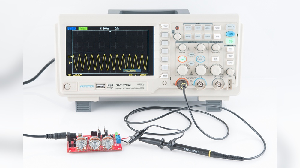
Connecting Probes Correctly
Attach the probe to the oscilloscope’s input channel. Make sure the connection is firm and secure. Connect the probe tip to the test point in your circuit. Attach the ground clip to the circuit’s ground.
Double-check the probe settings on the oscilloscope. Match the probe attenuation with the device setting for accurate readings.
Calibrating The Device
Calibration ensures the oscilloscope shows correct voltage levels. Use the built-in calibration signal if available. Connect the probe to the calibration output.
Adjust the vertical scale and position until the waveform matches the expected shape. Fine-tune the horizontal time base to see the signal clearly.
Repeat calibration regularly for reliable measurements.
Probe Handling Techniques
Handling oscilloscope probes correctly is key to getting accurate readings. Poor probe handling can cause errors and signal problems. Follow simple techniques to keep your measurements clean and reliable. These steps help protect your device and improve your work quality.
Choosing The Right Probe
Pick a probe that matches your signal type and frequency. Use a low-voltage probe for sensitive circuits. High-voltage probes protect you from strong signals. The probe’s bandwidth should cover your signal’s frequency. Using the wrong probe can distort the signal or damage the oscilloscope.
Minimizing Signal Distortion
Keep the probe tip close to the test point. Avoid long ground leads; they add noise and distortion. Use a short, direct connection for the ground clip. Hold the probe steady to prevent movement. Make sure the probe’s compensation is adjusted before measuring.
Proper Grounding Methods
Attach the ground clip to a solid, clean ground point. A bad ground connection creates noise and false readings. Avoid using the oscilloscope’s chassis as a ground. Use the shortest possible ground lead to reduce interference. Check grounding before starting any measurement.
Configuring Measurement Parameters
Configuring measurement parameters is the first step to get clear and accurate readings on an oscilloscope. Setting these parameters correctly helps you see the signal details clearly. It also prevents confusion caused by unclear or unstable waveforms. Adjusting the right settings lets you analyze signals with ease and confidence.
Adjusting Time Base And Voltage Scale
The time base controls how fast the signal moves across the screen. Set it to show enough cycles of the waveform for better analysis. The voltage scale adjusts the height of the signal on the screen. Change it to fit the signal amplitude within the display range. Both settings should match the signal’s speed and strength.
Trigger Settings For Stable Waveforms
Trigger settings lock the waveform in place. This stops the signal from moving side to side. Choose the right trigger type, such as edge or pulse, based on your signal shape. Set the trigger level to catch the exact point where the signal starts. This ensures a steady and repeatable waveform on the screen.
Using Cursors And Measurement Tools
Cursors help measure time intervals and voltage differences easily. Move them along the waveform to mark points of interest. Use built-in measurement tools to get data like frequency, period, and peak voltage. These tools provide quick and precise results without manual calculations.
Capturing And Analyzing Signals
Capturing and analyzing signals is the core of using an oscilloscope effectively. The device helps visualize electrical signals so you can study their behavior clearly. Understanding how to capture signals properly ensures accurate and useful data. Analysis then reveals the signal’s characteristics, which is essential for troubleshooting or design.
Good signal capture requires choosing the right acquisition mode. Analysis depends on reading waveforms and spotting irregularities. Noise and interference often hide important details, so identifying them is key to clear results.
Single-shot Vs Continuous Acquisition
Single-shot acquisition captures one event at a time. It is useful for rare or one-time signal changes. Continuous acquisition records signals over time, showing ongoing behavior. This mode suits signals that repeat or change slowly. Choose single-shot for precision and continuous for monitoring trends.
Interpreting Common Waveforms
Waveforms like sine, square, and triangle are basic shapes seen on oscilloscopes. Each shape tells about signal type and source. Sine waves indicate smooth, periodic signals. Square waves show digital or switching signals. Triangle waves suggest linear changes. Learn these shapes to understand signal function quickly.
Identifying Noise And Interference
Noise appears as random fluctuations on the signal. Interference often shows as unwanted spikes or patterns. Both can hide true signal details. Use filters and proper grounding to reduce noise. Spotting interference helps find its source and fix the issue. Clean signals lead to better analysis and results.
Advanced Techniques
Advanced techniques help users get more from oscilloscopes. These methods improve measurement accuracy and data handling. They also boost efficiency when analyzing signals. Learning these skills makes complex tasks easier and faster.
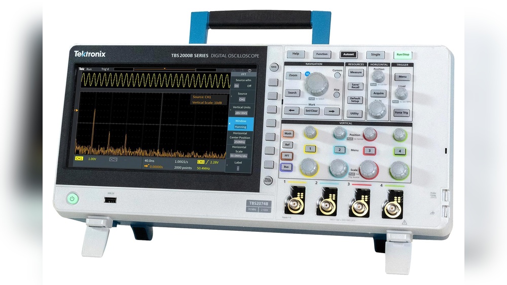
Using Math Functions
Math functions let you process signals directly on the oscilloscope. You can add, subtract, multiply, or divide waveforms. This helps find differences or combined effects between signals. Some oscilloscopes offer FFT to view signal frequencies. Using math functions reduces the need for extra tools.
Saving And Exporting Data
Saving data lets you keep important measurements for later use. Oscilloscopes allow saving screenshots or raw data. Export options include USB drives or network locations. Exported data can be analyzed on a computer. This is useful for reports and deeper signal study.
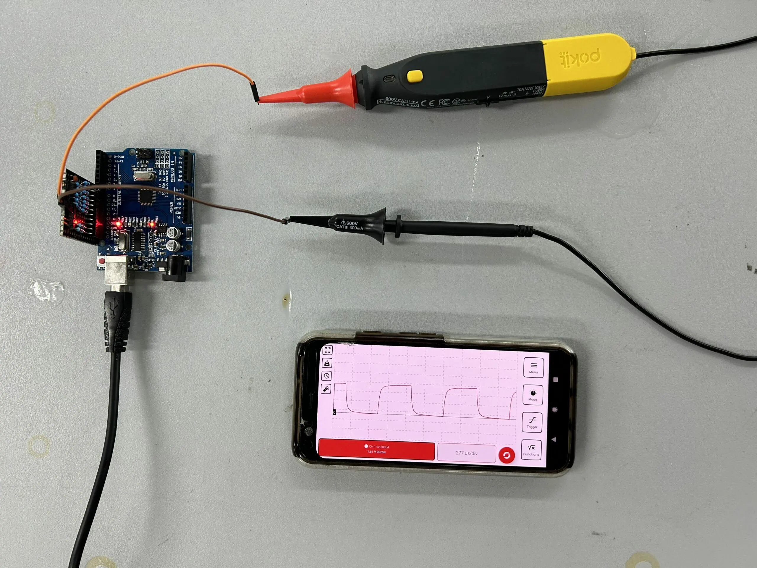
Remote Operation And Automation
Remote operation enables control of the oscilloscope from a computer. It helps run tests without physical presence. Automation scripts can perform repeated measurements automatically. This saves time and reduces human error. Many scopes support standard protocols for easy integration.
Troubleshooting Tips
Troubleshooting an oscilloscope can save time and improve your results. Many issues arise from simple mistakes. Knowing what to check first helps you fix problems fast. This section covers common setup errors, signal integrity problems, and tips for keeping readings accurate.
Common Setup Errors
Incorrect connections cause many oscilloscope problems. Make sure the probe is securely attached to the test point. Check that the probe ground clip is connected to the circuit ground. Set the oscilloscope to the right voltage and time scale for your signal. Using the wrong settings can hide or distort the waveform. Verify the probe attenuation matches the oscilloscope input settings. A mismatch leads to wrong voltage readings.
Signal Integrity Issues
Noisy or unstable signals confuse analysis. Keep probe leads short and avoid loose connections. Long wires pick up interference from other electronics. Use shielded cables to reduce noise. Be aware of the bandwidth limit of your oscilloscope and probes. Signals outside this range appear distorted. Check the circuit for any bad connections or faulty components causing signal problems.
Maintaining Accurate Readings
Calibration ensures your oscilloscope shows correct values. Perform regular calibration checks using a known signal source. Zero the vertical offset before measuring. Drift in settings can cause errors over time. Clean the probe tips and connectors to maintain good contact. Avoid touching the probe tip during measurements to reduce noise. Power the oscilloscope from a stable source to prevent voltage fluctuations.
Credit: www.youtube.com
Frequently Asked Questions
What Is The Main Purpose Of An Oscilloscope?
An oscilloscope visually displays electrical signals as waveforms. It helps analyze signal voltage, frequency, and timing in circuits. Engineers use it to troubleshoot and verify electronic devices efficiently.
How Do I Connect Probes To An Oscilloscope?
Attach the probe’s tip to the test point and the ground clip to the circuit ground. This ensures accurate signal measurement and avoids noise interference during testing.
What Settings Should I Adjust First On An Oscilloscope?
Start by setting the time base and voltage scale. Adjust these to clearly view the waveform without distortion or clipping for better analysis.
How Can I Measure Signal Frequency Using An Oscilloscope?
Use the oscilloscope’s time base to measure one complete waveform cycle. Frequency equals the inverse of the period, calculated from the time measurement.
Conclusion
Working with an oscilloscope becomes easier with practice and patience. Start by learning the basic controls and settings. Focus on reading waveforms clearly and adjusting the time and voltage scales. Always connect the probes carefully to avoid errors. Keep the screen clean and organized for better results.
Remember, every measurement helps you understand circuits better. Use the oscilloscope regularly to build confidence. Small steps lead to great progress. Soon, you will feel comfortable analyzing signals and solving problems with ease.

I’m Asif Ur Rahman Adib, an Electrical Engineer and lecturer. My journey began in the lab, watching students struggle with instruments they used every day without fully understanding them. Over time, I’ve combined teaching, research, and hands-on experience to help others grasp electrical concepts clearly, safely, and practically—whether it’s understanding a circuit or mastering a multimeter.