Are you struggling to understand the difference between AC and DC coupling on your oscilloscope? Knowing when and how to use each can make a huge difference in your measurements.
Whether you’re troubleshooting circuits or capturing signals, choosing the right coupling mode helps you see exactly what you need—no more confusing waveforms or missed details. Keep reading, and you’ll learn how to master AC vs DC coupling on your oscilloscope, making your work faster, clearer, and more accurate.

Credit: www.youtube.com
Basics Of Ac And Dc Coupling
Understanding the basics of AC and DC coupling is essential for using an oscilloscope. These two coupling modes affect how signals are displayed on the screen. They help separate or combine different parts of the signal. Choosing the right coupling mode ensures accurate measurements and clear waveforms.
What Is Ac Coupling?
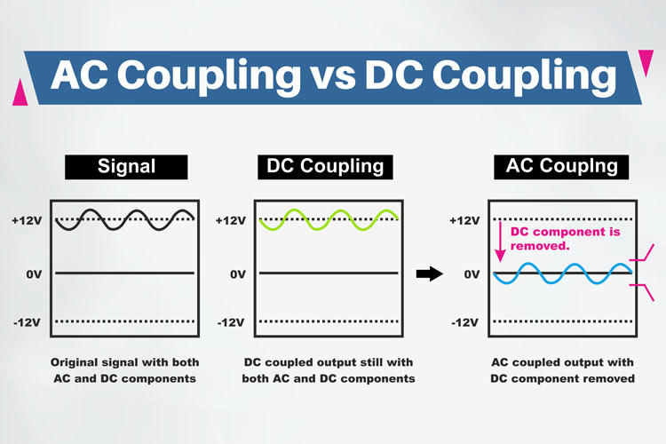
AC coupling blocks the direct current (DC) part of a signal. It lets only the alternating current (AC) part pass through. This mode removes any steady voltage or offset from the signal. It is useful for seeing small AC signals that ride on a large DC voltage. AC coupling uses a capacitor to filter out the DC component.
What Is Dc Coupling?
DC coupling allows both AC and DC parts of a signal to pass. It shows the full signal, including any offset or steady voltage. This mode is helpful for analyzing the complete waveform. It uses a direct connection without filtering any part of the signal. DC coupling is the default mode for most oscilloscope channels.
Signal Behavior With Ac Coupling
AC coupling in oscilloscopes changes how signals appear on the screen. It removes the steady parts of the signal, showing only the changing parts. This helps focus on the variations, making it easier to analyze certain signal behaviors. Understanding how signals behave with AC coupling is important for accurate measurement and analysis.
Filtering Out Dc Components
AC coupling blocks the DC part of a signal. The DC component is the constant voltage level. Removing this level allows the oscilloscope to show only the changes. This makes small variations easier to see. It helps avoid screen drift caused by large DC offsets. As a result, the displayed waveform centers around zero volts.
Impact On Low-frequency Signals
AC coupling affects low-frequency signals the most. It can reduce or distort slow-changing signals. Very low frequencies may appear smaller or altered. This happens because AC coupling uses a capacitor to block DC. The capacitor blocks signals below a certain frequency. Users should be careful when measuring slow signals with AC coupling. For accurate low-frequency readings, DC coupling is often better.
Signal Behavior With Dc Coupling
DC coupling in an oscilloscope shows the full signal, including both AC and DC parts. This method lets you see the real shape of the signal without any filtering. It is useful for signals that have a steady voltage level mixed with changing parts. Understanding signal behavior with DC coupling helps in many electronics tests and repairs.
Capturing Complete Signal Waveforms
DC coupling captures the entire waveform without cutting off any part. It shows the exact voltage level at all times. This helps detect small changes in the signal’s baseline. Both slow and fast changes in the signal appear clearly. Users get a true picture of the signal’s behavior over time.
Handling Dc Offsets
DC coupling shows the signal’s offset voltage clearly. This offset is the constant voltage added to the signal. It helps find issues like power supply problems or sensor errors. The oscilloscope displays these offsets without hiding them. This makes troubleshooting easier and more accurate.
When To Use Ac Coupling
AC coupling is a useful setting on an oscilloscope. It helps when you want to see only the changing part of a signal. This section explains when to use AC coupling in your measurements.
Observing Small Ac Signals On Large Dc Bias
Sometimes, a signal has a strong DC level with a small AC variation. AC coupling blocks the DC part. This makes the small AC signal easier to see. It improves the clarity of the waveform. You can focus on the changes, not the steady voltage. This is important in audio signals and sensor outputs.
Reducing Baseline Drift
Baseline drift happens when the signal moves slowly over time. It can make measurements less clear. AC coupling removes this slow change. It keeps the baseline steady on the screen. This helps in long-term monitoring and testing circuits. The oscilloscope shows only the fast, important changes.
When To Use Dc Coupling
DC coupling in oscilloscopes shows both AC and DC parts of a signal. It helps see the true shape of the waveform. Use DC coupling when the steady voltage level matters. It captures slow signals without losing details.
Measuring Dc Levels And Slow Signals
DC coupling shows the exact voltage level of a signal. It measures signals that change slowly or stay steady. This is important for battery tests or sensor outputs. AC coupling would block these steady parts. DC coupling helps track voltage shifts over time.
Analyzing Waveform Details
Use DC coupling to see all waveform details clearly. It shows small changes on top of a DC level. This helps in checking digital signals or power supplies. You can spot tiny issues that AC coupling might hide. DC coupling gives a full picture of the signal shape.
Pros And Cons Of Ac Coupling
AC coupling is a common feature in oscilloscopes. It allows the device to block direct current (DC) components of a signal. This helps focus on the alternating current (AC) parts. Understanding the pros and cons of AC coupling helps users choose the right setting for their needs.
AC coupling is useful for analyzing small signals on a large DC offset. It filters out the DC level and lets the AC signal stand out. This makes it easier to see details in the waveform.
Advantages Of Ac Coupling
AC coupling removes any steady DC voltage from the signal. This prevents the waveform from being shifted vertically on the screen. It allows clearer observation of changes in the signal over time.
It is ideal for measuring small AC signals on top of large DC voltages. This makes it easier to detect noise or ripple in power supplies. It also reduces the chance of damaging the oscilloscope input from high DC voltages.
Disadvantages Of Ac Coupling
AC coupling blocks all DC information in the signal. This means users cannot measure the true DC level or offset. It may cause distortion of slow signals or waveforms with low frequency.
Sometimes, the signal baseline may drift or appear unstable. This happens because the DC component is removed and the scope tries to adjust the zero level. It can confuse users who need accurate DC measurements.
Pros And Cons Of Dc Coupling
DC coupling is a common mode used in oscilloscopes to measure signals. It allows direct measurement of both AC and DC components of a signal. This feature makes DC coupling useful for many types of electronic testing and troubleshooting. Understanding its strengths and weaknesses helps in choosing the right coupling mode for your task.
Advantages Of Dc Coupling
DC coupling shows the full signal, including the steady DC level. This helps identify any offset in the signal easily. It is perfect for measuring low-frequency signals or signals with a DC bias. You can observe the true waveform without losing any part of the signal. This mode also helps in tracking slow changes in voltage over time.
Disadvantages Of Dc Coupling
DC coupling can introduce noise from the DC component. This noise may make small AC signals harder to see. It is not ideal for high-frequency signals because of possible drift. Sometimes, the DC offset can saturate the oscilloscope input. This saturation causes distortion or clipping of the waveform. Extra care is needed to set the vertical scale correctly.

Credit: electronics.stackexchange.com
Practical Examples
Understanding how to use AC vs DC coupling on an oscilloscope helps in many real-world tasks. Each type of coupling shows signals in a unique way. This makes it easier to analyze different kinds of electronic signals. Below are some practical examples to show how each coupling type works in daily testing and troubleshooting.
Testing Audio Signals
Audio signals often have both AC and DC parts. Using AC coupling blocks the DC part. This shows only the sound wave itself. It helps in checking the clarity and shape of the audio signal. If you want to see the full signal, use DC coupling. This shows the DC offset and sound wave together. It is useful when adjusting audio equipment for best performance.
Troubleshooting Power Supplies
Power supplies provide DC voltage but may have AC noise. Using DC coupling shows the steady voltage level. This helps confirm the power supply works properly. AC coupling reveals small noise and ripple on the voltage. This noise can cause problems in sensitive circuits. Finding and fixing this noise improves device stability and performance.
Tips For Choosing Coupling Mode
Choosing the right coupling mode on an oscilloscope is key to getting clear signal readings. AC and DC coupling affect how the oscilloscope shows the signal. Selecting the best mode depends on the signal type and what you want to measure. Here are some helpful tips to guide your choice of coupling mode.
Consider Signal Frequency
AC coupling blocks DC components and passes only changing signals. It works well for high-frequency signals. DC coupling shows both AC and DC parts of the signal. It suits low-frequency or steady signals. Match the coupling mode to the frequency to avoid missing important details.
Account For Dc Offset
DC offset shifts the signal baseline up or down. Use DC coupling to see this offset clearly. AC coupling removes the offset, centering the waveform around zero. Check if the offset matters for your measurement before selecting the mode.
Adjusting Oscilloscope Settings
After choosing the coupling mode, fine-tune other settings. Adjust the vertical scale to fit the signal size. Set the time base to capture signal changes properly. Proper settings help get accurate and easy-to-read waveforms.
Credit: components101.com
Frequently Asked Questions
What Is Ac Coupling In An Oscilloscope?
AC coupling blocks the DC component of a signal. It allows only the AC or varying part to be displayed. This helps analyze small AC signals superimposed on a large DC offset.
How Does Dc Coupling Work On An Oscilloscope?
DC coupling shows both AC and DC components of a signal. It provides the true waveform including any steady voltage level. This mode is useful for measuring total voltage levels.
When Should I Use Ac Vs Dc Coupling?
Use AC coupling to view small AC signals on large DC offsets. Use DC coupling to observe the full waveform including DC levels. Choice depends on the signal type and measurement goal.
Can Ac Coupling Distort Low-frequency Signals?
Yes, AC coupling may distort or block low-frequency signals below its cutoff frequency. It acts like a high-pass filter, removing slow signal changes. Use DC coupling for accurate low-frequency measurements.
Conclusion
Choosing between AC and DC coupling on an oscilloscope depends on your test needs. AC coupling blocks DC signals, letting you see small changes better. DC coupling shows the full signal, including DC parts. Each mode helps you understand signals differently.
Use the right coupling to get clear, accurate results. This simple step can improve your measurements. Keep practicing, and you will get better at using your oscilloscope. Small details matter in electronics testing.

I’m Asif Ur Rahman Adib, an Electrical Engineer and lecturer. My journey began in the lab, watching students struggle with instruments they used every day without fully understanding them. Over time, I’ve combined teaching, research, and hands-on experience to help others grasp electrical concepts clearly, safely, and practically—whether it’s understanding a circuit or mastering a multimeter.