When you’re working with an oscilloscope, choosing between 1X and 10X probes can feel confusing. You might wonder which one gives you clearer signals or more accurate readings.
The truth is, picking the right setting can change everything about how you see and understand your measurements. If you want to get the most from your oscilloscope and avoid common mistakes that waste time and cause frustration, this guide is for you.
Keep reading to discover the key differences between 1X and 10X probes, and learn how to use each one like a pro. Your next test could be sharper and more reliable than ever before.
Basics Of Oscilloscope Probes
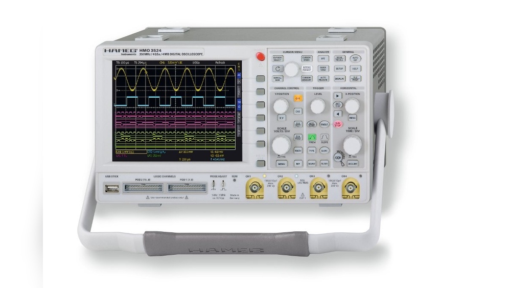
Oscilloscope probes are important tools for measuring electrical signals. They connect the oscilloscope to the circuit being tested. Choosing the right probe affects the accuracy of your readings. Understanding the basics helps you use your oscilloscope better.
Probes come in different types and styles. Each type has a special role in how it measures signals. Knowing these details helps you pick the best probe for your task.
Types Of Probes
There are several common types of oscilloscope probes. The 1X probe is simple and does not change the signal much. It has low attenuation but can load the circuit. The 10X probe reduces the signal by ten times. It adds less load to the circuit and protects the oscilloscope. Other probes include active and differential probes for special uses. Each type suits different measurement needs.
Role In Signal Measurement
Probes affect signal quality and accuracy. The 1X probe gives a stronger signal but can distort it. The 10X probe weakens the signal but keeps it cleaner. It also allows measuring higher voltages safely. Using the right probe reduces noise and errors. This helps to see the true shape of the signal on the screen.

Credit: www.youtube.com
What Is 1x Probe Attenuation
1X probe attenuation is a setting on oscilloscope probes that affects how signals are measured. It means the probe does not reduce or weaken the signal strength. The signal you see on the oscilloscope screen is the same as the signal at the test point.
This setting is common for basic measurements and low-frequency signals. It helps users see the signal clearly without any change in size. Understanding 1X probe attenuation is important for choosing the right probe for your test.
Characteristics And Uses
1X probes provide a direct signal with no reduction. They have low input impedance, usually around 1 megaohm. This can affect the circuit being tested.
These probes work well for low-frequency signals below 10 MHz. They are simple and easy to use. Ideal for checking battery voltage or low-speed digital signals.
1X probes do not need special calibration. This makes them good for quick tests and learning purposes.
Signal Impact
Using a 1X probe can load the circuit more than higher-attenuation probes. The low input impedance draws more current from the circuit. This may change the signal slightly.
At high frequencies, 1X probes show distortion or signal loss. The cable and probe capacitance affect the signal shape. This can lead to inaccurate measurements on fast signals.
For clean and precise signals, 10X probes are better. But 1X probes still serve well for simple and slow signals.
What Is 10x Probe Attenuation
10X probe attenuation is a common setting on oscilloscope probes. It reduces the signal voltage by a factor of ten before it reaches the oscilloscope input. This helps measure higher voltages safely and accurately. The probe divides the input voltage, so the oscilloscope can handle stronger signals without damage. It also affects signal quality and measurement accuracy. Understanding 10X probe attenuation helps you choose the right setting for your tests.
Features And Benefits
10X probes have a built-in resistor that reduces the signal strength. This keeps the oscilloscope safe from high voltage. The probe also lowers the load on the circuit being tested. This means the circuit works normally without interference. It increases the input impedance of the probe, which improves measurement accuracy. The higher impedance reduces signal distortion. You get clearer, more reliable readings. The probe cable is designed to reduce noise and interference. This helps maintain signal integrity during measurement.
Effect On Waveforms
Using a 10X probe changes the waveform amplitude on the screen. The oscilloscope shows a signal that is one-tenth of the original voltage. You must multiply the reading by ten to get the true value. The probe can reduce high-frequency noise in the waveform. This makes the signal look smoother and cleaner. However, it may slightly affect signal rise time and shape. Proper compensation of the probe is needed to avoid waveform distortion. Without compensation, the waveform may appear rounded or fuzzy. Correct use of a 10X probe gives accurate, clear waveforms for analysis.
Comparing Signal Accuracy
Comparing signal accuracy between 1X and 10X oscilloscope probes helps choose the right tool. Signal accuracy affects how well your oscilloscope shows the real waveform. Small differences in probes can change measurement results. Understanding these differences improves test quality and saves time.
Bandwidth Considerations
Bandwidth defines the range of frequencies a probe can handle. A 10X probe usually has higher bandwidth than a 1X probe. Higher bandwidth means better accuracy for fast signals. A 1X probe may miss or distort high-frequency details. Choosing a probe with enough bandwidth ensures clearer signals.
Signal Distortion Factors
Signal distortion occurs when the probe changes the waveform shape. A 1X probe has more load on the circuit, causing more distortion. The 10X probe reduces load, preserving the original signal shape. Cable length and quality also affect distortion. Using the right probe lowers measurement errors and improves results.
Choosing Between 1x And 10x
Choosing between 1X and 10X settings on an oscilloscope probe affects your measurement quality. Each setting changes how signals are displayed and how much the probe affects the circuit. Picking the right option helps you get clear, accurate readings without damaging your circuit or losing detail.
When To Use 1x
Use 1X for low-frequency signals and simple tests. This setting does not reduce the signal size, so you see the exact voltage. It works well for signals under 1 MHz. Also, 1X is good for checking battery levels or power supplies. It has less signal loss but can load the circuit more. Choose 1X when circuit loading is not a problem.
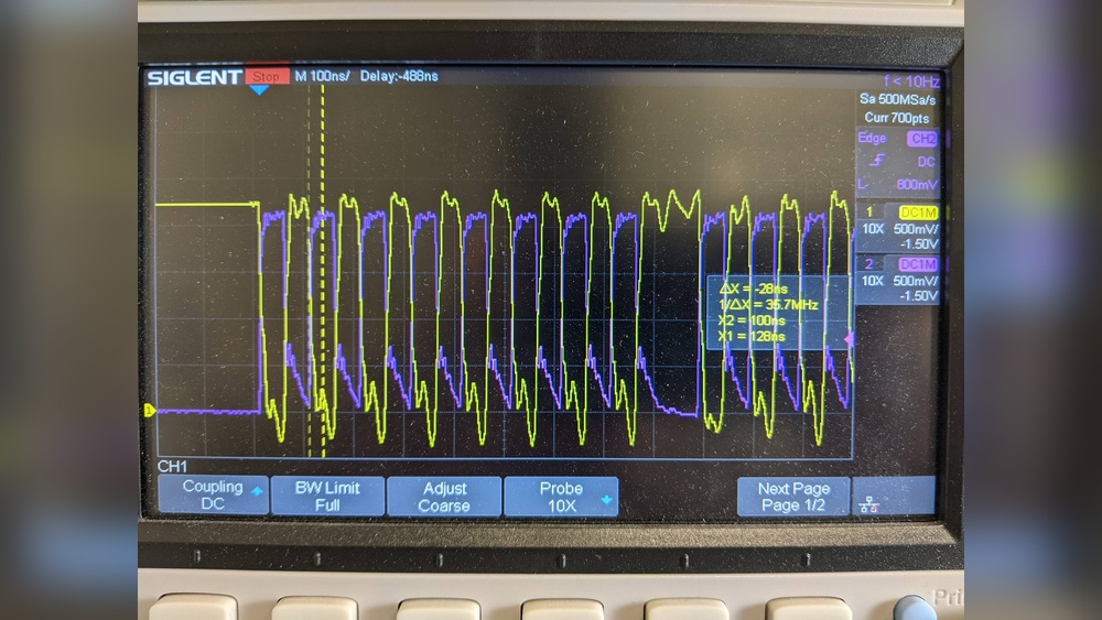
When To Use 10x
Use 10X for high-frequency signals and detailed analysis. This setting reduces the signal by ten times, preventing probe loading. It improves signal quality and bandwidth. Use 10X for signals over 1 MHz or when measuring fast pulses. It protects the circuit from excessive current. Choose 10X to get clearer, more accurate readings on complex signals.

Credit: electronics.stackexchange.com
Practical Tips For Accurate Measurements
Getting accurate measurements with an oscilloscope depends on careful setup and technique. Small mistakes can lead to wrong results and confusion. Simple actions can improve measurement quality. Focus on two key areas: probe compensation and reducing noise. These tips help you read signals clearly and reliably.
Proper Probe Compensation
Probe compensation matches the probe to the oscilloscope input. It prevents signal distortion. Use the calibration signal on the oscilloscope to adjust the probe. Connect the probe to the test point and adjust the compensation trimmer. The waveform should show a clean square wave without rounding or overshoot. Check compensation regularly. Different probes or cables may need new adjustments.
Minimizing Noise And Interference
Noise hides the real signal and causes errors. Keep probe ground leads short to reduce noise pickup. Avoid running probe cables near power lines or motors. Use shielded cables if possible. Turn off nearby devices that cause interference. Use a low-noise environment for testing. Proper probe placement and cable management keep your measurements clean.
Common Mistakes And How To Avoid Them
Using an oscilloscope probe with the wrong setting can cause errors. These mistakes affect measurement accuracy and can confuse users. Knowing common errors and how to fix them helps get clear readings.
This section explains typical mistakes made with 1X and 10X probe settings. It also offers simple tips to avoid these errors during tests.
Using 1x Setting For High-frequency Signals
The 1X setting has more capacitance and less bandwidth. It distorts high-frequency signals and reduces measurement accuracy. Always check the signal frequency before choosing the 1X mode. Switch to 10X for better response on fast signals.
Ignoring Probe Compensation
Probes need proper compensation to match the oscilloscope input. Skipping this step causes waveform distortion and wrong amplitude readings. Use the oscilloscope’s built-in square wave to adjust the probe’s compensation trimmer. Regularly check this adjustment to keep signals sharp.
Forgetting Attenuation Settings In Measurements
The 10X probe reduces signal amplitude by ten times. Forgetting this leads to incorrect voltage readings. Always set the oscilloscope input attenuation to match the probe’s setting. This step ensures displayed values are accurate and easy to read.
Not Using The Proper Ground Connection
Using the wrong ground point creates noise and false signals. Connect the probe ground clip to a stable, low-resistance ground nearby. Avoid long ground leads to reduce interference. Proper grounding improves signal clarity and measurement reliability.
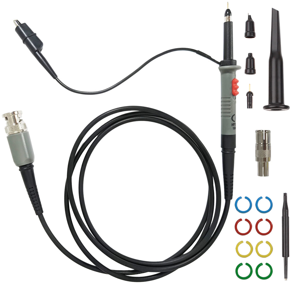
Credit: www.elexp.com
Frequently Asked Questions
What Is The Difference Between Oscilloscope 1x And 10x Probes?
Oscilloscope 1X probes provide direct signal measurement with no attenuation. 10X probes attenuate the signal by ten times, reducing loading effect and improving accuracy for higher frequency signals.
When Should I Use A 1x Probe Over A 10x Probe?
Use a 1X probe for low-frequency signals or high amplitude measurements. A 10X probe is better for high-frequency signals or when minimizing circuit loading is critical.
How Does A 10x Probe Affect Signal Accuracy?
A 10X probe reduces signal amplitude by tenfold, which lowers loading and improves accuracy. It minimizes distortion and interference in high-frequency or sensitive circuits.
Can I Use A 1x Probe For High-frequency Signals?
Using a 1X probe on high-frequency signals can cause signal distortion and loading errors. A 10X probe is recommended for better signal integrity at high frequencies.
Conclusion
Choosing between 1X and 10X probes depends on your testing needs. Use 1X for low-frequency signals and simple checks. Switch to 10X when you need better signal clarity and less noise. Each has its strengths in different situations. Understanding these helps you get accurate oscilloscope readings.
Experiment with both to see what fits your work best. This knowledge makes your measurements clearer and more reliable. Keep practicing, and your oscilloscope skills will improve steadily.

I’m Asif Ur Rahman Adib, an Electrical Engineer and lecturer. My journey began in the lab, watching students struggle with instruments they used every day without fully understanding them. Over time, I’ve combined teaching, research, and hands-on experience to help others grasp electrical concepts clearly, safely, and practically—whether it’s understanding a circuit or mastering a multimeter.