When you’re working with oscilloscopes, understanding impedance is crucial for getting accurate readings. But how does oscilloscope impedance compare to LCX cables?
This difference can directly affect your measurements and the quality of your results. If you’ve ever wondered why your signals look off or why noise creeps in, the answer might lie in how these two components interact. Keep reading, and you’ll discover exactly what you need to know to optimize your setup and get the clear, reliable data you want every time.

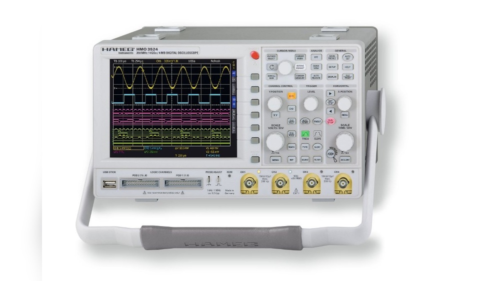
Credit: www.batronix.com
Basics Of Oscilloscope Impedance
Oscilloscope impedance is a key factor in measuring electrical signals accurately. It shows how much the oscilloscope resists the flow of electric current. Understanding this helps in choosing the right settings and tools for testing circuits.
Wrong impedance can change the signal shape or size. This makes readings unreliable. Knowing the basics helps avoid these problems and improves measurement quality.
Input Impedance Types
Oscilloscopes usually have two main input impedance types: 1 megaohm and 50 ohms. The 1 megaohm input is common for general use. It has a high resistance and low current flow. The 50-ohm input matches the impedance of some cables and devices.
Each type suits different tasks. High impedance inputs prevent signal loading. Low impedance inputs reduce noise in high-frequency signals.
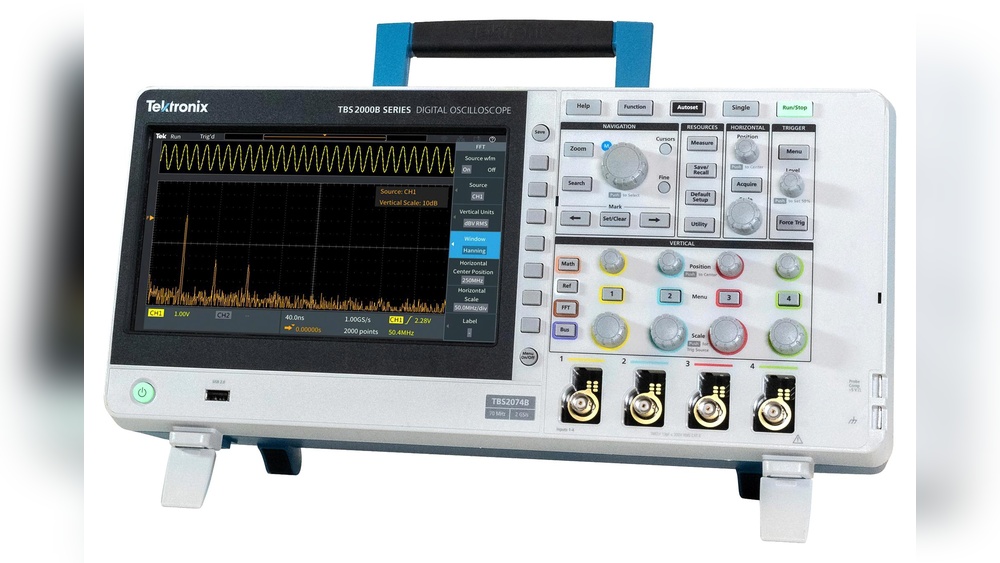
Impact On Signal Measurement
Impedance affects how the oscilloscope interacts with the signal source. A mismatch can cause signal loss or distortion. High input impedance prevents drawing too much current from the circuit.
Low impedance inputs help maintain signal integrity at high frequencies. Choosing the right impedance improves accuracy and protects the device under test.
Credit: www.batronix.com
What Is Lcx Cable?
LCX cable is a type of coaxial cable used in many electronic measurements. It offers stable impedance and low signal loss. This makes it popular for connecting oscilloscopes and other test devices. Understanding LCX cable helps in choosing the right tool for accurate signal testing.
Construction And Characteristics
LCX cable has a unique build that ensures good signal quality. It includes a central conductor surrounded by a dielectric insulator. Around this, a shielding layer blocks outside noise. The outer jacket protects the cable from damage and wear. Its impedance is usually 50 ohms, matching many test instruments. This design reduces signal reflection and loss during measurements.
Common Uses In Measurement
LCX cables are common in high-frequency signal testing. They connect oscilloscopes to devices under test. These cables help capture accurate signals without distortion. Engineers use LCX cables in labs and field tests alike. They are ideal for radio frequency and microwave measurements. Their stable impedance ensures reliable test results every time.
Comparing Oscilloscope Impedance And Lcx
Comparing oscilloscope impedance and LCX reveals key differences in how each handles electrical signals. Both play crucial roles in measuring and transmitting signals, but their properties impact performance. Understanding these differences helps choose the right tool for accurate signal analysis.
Electrical Properties
Oscilloscope impedance usually matches standard values like 50 ohms or 1 megaohm. LCX, a type of coaxial cable, has a fixed characteristic impedance, often 50 ohms. This impedance controls how signals travel without reflection or loss. Mismatched impedance can cause signal distortion or weak measurements.
Signal Integrity Effects
Proper impedance maintains signal strength and shape. Oscilloscopes with correct input impedance reduce noise and distortion. LCX cables preserve signal quality over distance by minimizing interference. Using the right impedance for both oscilloscope and cable ensures clear, reliable data.
Frequency Response Differences
Oscilloscope input impedance affects the frequency range it can handle accurately. LCX cables support high frequencies with low loss and minimal delay. However, cable length and quality influence the signal’s frequency response. Matching impedance helps keep signals true across frequencies.
Practical Implications For Testing
Understanding oscilloscope impedance versus LCX cables is key for accurate testing. These factors affect signal quality and measurement results. Poor choices can cause errors and misreadings. Knowing the practical implications helps improve your testing process.
Choosing The Right Setup
Select an oscilloscope with input impedance matching your signal source. Most oscilloscopes have 1 MΩ or 50 Ω inputs. Use 1 MΩ for high-impedance signals to avoid loading effects. Use 50 Ω inputs for high-frequency or RF signals to reduce reflections.
Choose LCX cables with proper impedance to match the oscilloscope input. Mismatched impedance causes signal loss and distortion. Shorter cables reduce noise and signal degradation. Ensure connectors are secure and clean for stable connections.
Minimizing Measurement Errors
Always calibrate your oscilloscope before testing. Calibration adjusts for internal impedance and cable effects. Use probe compensation to match probe capacitance with the oscilloscope input. This prevents waveform distortion and inaccurate readings.
Keep cables away from power lines or electromagnetic sources. These can induce noise and affect signal integrity. Use shielded LCX cables for better noise rejection. Check connections regularly to avoid intermittent faults.
Tips For Accurate Oscilloscope Readings
Accurate oscilloscope readings depend on many factors. The right setup helps capture signals clearly and correctly. Small mistakes can cause errors and confusion. Use these tips to improve your measurement accuracy and trust your results.
Proper Probe Selection
Choose probes that match your oscilloscope’s impedance. A 10x probe reduces loading on the circuit. It keeps signal distortion low and preserves waveform shape. Use low-capacitance probes for high-frequency signals. Check probe compensation before each use to avoid errors. A well-matched probe ensures clean and reliable data.
Cable Management Best Practices
Keep cables short and neat to reduce noise pickup. Avoid tangled or twisted cables near power sources. Use shielded cables to block interference from nearby devices. Secure cables away from moving parts and sharp edges. Proper cable routing helps maintain signal integrity. Clean connections and check for damage regularly to prevent signal loss.
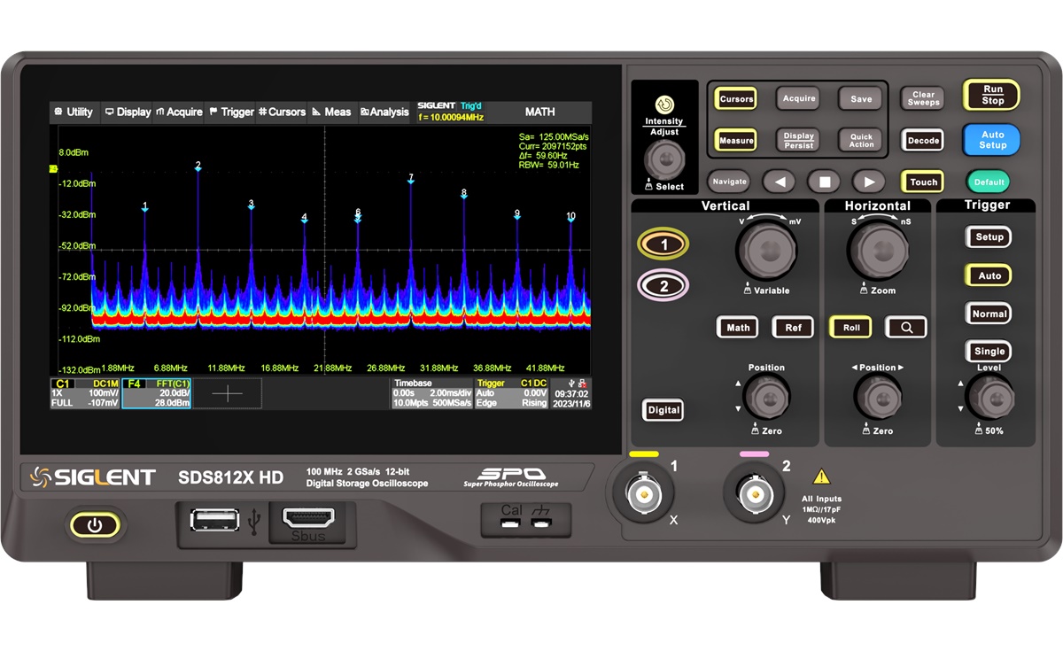
Credit: passive-components.eu
Frequently Asked Questions
What Is Oscilloscope Impedance And Why Is It Important?
Oscilloscope impedance is the resistance and reactance the device offers to signals. It affects signal accuracy and measurement quality, making it crucial for precise electronic testing and analysis.
How Does Lcx Affect Oscilloscope Input Impedance?
LCX, a type of coaxial cable, adds capacitance and resistance to the oscilloscope input. This changes the overall impedance, impacting signal integrity and measurement fidelity.
Why Match Oscilloscope Impedance With Test Circuit Impedance?
Matching impedances minimizes signal reflections and loss. This ensures accurate waveform capture and reliable data during oscilloscope measurements.
Can Mismatched Impedance Damage Oscilloscope Or Circuit?
Yes, impedance mismatch can cause signal distortion and potential damage. It stresses both the oscilloscope and the tested circuit components.
Conclusion
Choosing the right impedance for your oscilloscope matters. It affects signal quality and measurement accuracy. Low impedance loads can change the circuit behavior. High impedance helps keep signals intact. Consider the LCX cable’s characteristics too. It impacts how signals travel and reflect.
Match impedance values carefully for best results. This balance ensures clear, reliable readings. Understanding these basics makes testing easier. Keep these tips in mind for better oscilloscope use.

I’m Asif Ur Rahman Adib, an Electrical Engineer and lecturer. My journey began in the lab, watching students struggle with instruments they used every day without fully understanding them. Over time, I’ve combined teaching, research, and hands-on experience to help others grasp electrical concepts clearly, safely, and practically—whether it’s understanding a circuit or mastering a multimeter.